
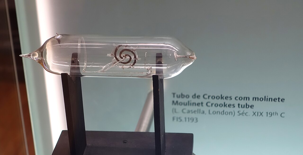
A Casella moulinet Crookes tube
An intricate glass demonstration instrument attributed to L. Casella, London.

- Electrical family
- Low-pressure gas-discharge and cathode-ray apparatus
- Central question
- What travels from the cathode, and how can its behaviour be tested?
- Historical focus
- Crookes’s 1870s demonstrations and the investigations leading to Thomson’s 1897 paper
- Gallery variants
- Magnetic deflection; butterfly form; Casella moulinet
The photographed apparatus
The file record identifies this as a nineteenth-century moulinet Crookes tube by L. Casella of London, displayed at the Museu da Ciência da Universidade de Coimbra. Daderot photographed the exhibit on 4 November 2019. Its long glass form and internal mechanism make it a particularly good example of the ingenious shapes produced for electrical demonstration and investigation. The object identification comes from the collection photograph’s title; a more precise manufacture date is not supplied there.
The point of including it is to look closely at an actual experimental instrument. The term moulinet draws attention to the mechanism inside the tube, while the enclosing glass places it within the broader history of evacuated electrical apparatus. It should be presented with that identity intact, rather than recast as an electrode or a healing machine because it shares a luminous-tube ancestry. Alongside a violet-ray electrode atlas, the photograph demonstrates how varied the glassworker’s and instrument maker’s solutions could become. Its reuse is supported by the photographer’s CC0 dedication, and its source record provides a route back to the museum, maker attribution and modern photographic date.
Making an invisible cause leave a visible signature
The Crookes tube begins with a compelling experimental bargain: the thing under investigation may be invisible, provided its effects can be made visible. Inside a carefully prepared glass vessel, electricity produces patches of light, shadows, heating or motion. Different internal arrangements isolate different questions. A screen turns a path into a luminous trace; an obstacle interrupts it; a magnet changes its direction. The remarkable glass shapes are part of that reasoning. They place a source, a proposed path and a revealing object in a relationship that an audience can inspect.
William Crookes’s 1879 lecture, On Radiant Matter, communicates the excitement of this approach. His demonstrations explore a territory where familiar categories appeared to fail. He interpreted the effects through rapidly moving, negatively electrified molecules in highly rarefied gas. Modern electron physics supplies a different and more specific account of cathode rays. Keeping both explanations in view reveals the historical achievement: Crookes made phenomena reproducible and vivid even while their ultimate interpretation was still contested.
That distinction is central to enjoying the apparatus. A green patch on glass is an observation. A claim about what crossed the vessel to produce it is an explanation. A further experiment must connect the two. The tube’s visual beauty is therefore inseparable from a demanding intellectual task: designing circumstances in which an unseen cause leaves a signature that competing explanations can be asked to account for.
An invention shared with the instrument maker
The family name can make the history sound like the work of one pair of hands. Surviving instruments restore the makers. The Science Museum’s magnetic-deflection tube, dated within 1878–1888, names Crookes as inventor and Charles H. Gimingham as maker. The distinction matters. An idea about a ray needs a vessel that holds its vacuum, electrodes that remain correctly positioned, and internal structures that can survive assembly. Glassworking and experimental imagination meet in the finished object. A small change in construction can decide whether an argument becomes a convincing demonstration.
Commercial instrument firms then carried such arrangements into other laboratories and teaching rooms. The Casella name on the gallery’s moulinet belongs to this wider craft and supply network. A separate Casella radiant-matter tube preserved at Cambridge’s Whipple Museum, dated around 1885, provides a useful comparison: its central paddle wheel and magnetic response show how specialised experimental arrangements became instruments that could circulate. Its date belongs to that Cambridge object; it cannot date the photographed Coimbra specimen.
This is a particularly satisfying way to read an apparatus gallery. Shape, maker and provenance belong beside the famous investigator. A tube is also a compact record of labour: pumping, sealing, mounting, testing and eventually teaching. The polished demonstration condenses all of that effort into a moment when an audience sees something unexpected happen. Giving the maker a place in the story restores some of the work that the effect itself tends to conceal.
The vacuum is an active part of the experiment
An old discharge tube is often described as empty, but its residual gas is crucial. Lower pressure generally lets a particle travel farther between collisions. At the same time, the gas supplies ions and electrons that help sustain a classic cold-cathode discharge. Positive ions can strike the cathode and release further electrons; electrons accelerate through the electrical field and interact with gas or solid surfaces. This is a changing system of particles and fields. Pressure, material and geometry all shape its behaviour.
Several sources of light can coexist. Excited gas can emit within the vessel, while electrons striking glass or a prepared coating can produce fluorescence at a surface. The luminous patch is consequently a detector response. Its colour depends on the emitting material and conditions; it is not the colour of an electron. A dark region may still contain electrical activity. Seeing the path requires a suitable interaction that converts some energy into visible light.
Thomson’s 1897 paper supplies a particularly revealing historical example of why the remaining gas matters. Conductivity in the gas could compromise an attempted electric-field deflection experiment, making a seemingly decisive absence of movement misleading. Better exhaustion changed the conditions of the test. In a museum case the glass looks still and complete. In the laboratory it enclosed a carefully controlled medium whose small remaining population of particles could alter both the effect and its interpretation.
A magnet turns the trace into a question
The gallery’s magnetic-deflection image is a modern demonstration photographed in 2015. Its source identifies a Crookes tube energised by a Ruhmkorff induction coil and a magnetic influence on the ray’s path. That date belongs to the photograph, while the instrument principle reaches back into nineteenth-century research. It is a valuable distinction: the image shows an apparatus family still capable of making a historical question visible, without pretending to be a photograph from Crookes’s own laboratory.
In modern terms, a moving electron experiences a magnetic force perpendicular to both its velocity and the magnetic field. A suitable field bends its path. An ideal magnetic field changes direction without itself supplying the electron’s kinetic energy; an electric field can accelerate or decelerate the particle. These are different interventions, which is why combining electrical and magnetic tests becomes so powerful. The direction of deflection, its magnitude and the electrical conditions together contain more information than a single curved glow.
A fluorescent screen is often the crucial translator. Harvard’s demonstration record describes a narrow beam arranged to strike a screen along its path, making magnetic displacement easy to observe. The apparatus effectively draws an argument for the viewer. Yet the visible trace still needs careful reading: screen position, field orientation and beam formation affect what is displayed. The strongest demonstration gives the observer a controlled change to compare, with the tube and detector remaining identifiable throughout.

The butterfly: a detector with a visual imagination
The butterfly tube makes the alliance between experiment and display especially clear. The gallery photograph records an exhibit at the University of Coimbra’s science museum; its file title identifies a nineteenth-century butterfly Crookes tube. The photograph was made in 2019. The surviving image record supports that identification and setting, while leaving the exact manufacture date, internal material and detailed operating history unresolved. Those limits are useful: they direct attention towards what the object can actually show us.
Within the wider instrument family, shaped fluorescent targets turn particle impact into a striking luminous design. A phosphor absorbs deposited energy and can release some of it as visible light. The efficiency, colour and persistence of that response depend on the material and its condition. The butterfly form provides a surface that is easy to recognise, so any illumination becomes immediately legible as an effect occurring in a particular internal object. Its theatrical shape helps the eye understand where something is happening.
The photographed specimen retains its own identity. General phosphor behaviour establishes neither the wings’ chemical composition nor their original brightness. The design also opens a rich historical question: how did instrument makers choose forms that could persuade and delight an audience? The butterfly gives that question a memorable body, bringing a natural silhouette into an unfamiliar electrical environment.

The moulinet: a moving wheel and a difficult explanation
The Casella moulinet introduces motion into the glass theatre. Its photo record identifies a nineteenth-century instrument by L. Casella of London, displayed at Coimbra and photographed in 2019. Moulinet directs attention to a small wheel or mill mechanism. Related railway tubes carry a wheel that can turn and travel inside the vessel, producing an effect with an almost irresistible intuitive explanation: something must be hitting the paddles and pushing them along.
Crookes used mechanical demonstrations to support his projected-matter interpretation. Electrons do carry momentum, but this familiar wheel is a poor clean measurement of their direct impulse. Harvard’s account summarises the later objection: energy deposited in the paddles produces thermal and radiometric effects involving the remaining gas, and direct electron momentum is insufficient to explain the observed movement. A real motion can therefore support the wrong simplified mechanism. That is precisely what makes the instrument so rewarding to study.
The lesson reaches beyond this particular design. A detector does something with the energy it receives. Its material, surrounding gas, temperature and freedom of movement become part of the result. To distinguish explanations, an experimenter needs comparisons that change these influences independently. The wheel’s charm survives the complication. Indeed, it becomes a richer object: the little mechanism reveals how readily the mind borrows a familiar model, and how an attractive demonstration can become the starting point for a much more discriminating experiment.
1897: turn the spectacle into a measurement
Thomson’s Cathode Rays begins with disagreement. Some physicists interpreted the rays as a process in the ether; others treated them as negatively charged material particles. His programme tested consequences of the particle view through several linked measurements. Charge collection, electric deflection and magnetic deflection could be made to tell a coherent story. The intellectual change is exhilarating: the apparatus becomes a means of inferring properties of something far too small to see directly.
A charge-to-mass ratio is especially revealing because it joins electrical response with inertia. A particle’s trajectory under a known field depends on its charge, mass and motion. Combining complementary effects can constrain quantities that a luminous picture alone leaves ambiguous. Comparing results under different conditions then asks whether the measured entity depends on the particular gas or electrode. The force of the argument comes from these relationships, rather than from any single dramatic visual effect.
This does not mean every Crookes tube was an electron-discovery instrument, nor that a gallery photograph reproduces Thomson’s measurement. It means the instrument family opened an experimental territory in which sharper questions became possible. Crookes’s radiant matter and Thomson’s corpuscles occupy different stages in that history. The name electron belongs to the account we now use. Following the changing vocabulary lets the reader experience the uncertainty that made the work necessary, instead of allowing hindsight to make the eventual answer seem obvious from the beginning.
From luminous curiosities to a new electrical world
The discharge-tube laboratory proved fertile in more than one direction. Röntgen’s 1895 preliminary account describes fluorescence produced near sufficiently exhausted discharge apparatus even when the tube was covered. His penetrating radiation was a different phenomenon from the cathode-ray stream inside the vessel. That distinction helped open a new field of investigation and imaging. Glass, electrodes and electrical excitation supplied a platform on which an unexpected observation could lead to a different question altogether.
Other tubes were designed to display heating, shadows or the response of luminous materials. Harvard preserves a demonstration replica with a metal target showing damage from concentrated heating. Such objects make the energy transfer unmistakable: the beam affects matter, and the target records that encounter. Later electron-beam instruments developed much more controlled sources, vacua and focusing systems. The conceptual inheritance is the ability to use charged particles and their interactions as tools for measurement, display and investigation.
In this gallery the three variants offer complementary pleasures. The magnetic tube turns a field into a visible change of direction. The butterfly joins detection with ornament. The moulinet asks why movement occurs. Their kinship with violet-ray glass lies in a shared historical fascination with electrical effects inside prepared vessels; their individual purposes still matter. That is what makes the collection engaging at close range. Every shape promises a different experiment, and every experiment offers a route from immediate wonder to a more precise question.
The development timeline
1870s · High exhaustion opens a new experimental territory
Crookes investigates electrical discharge in highly rarefied gas, using specially shaped vessels to compare luminous, thermal and mechanical effects.
1879 · Radiant matter reaches a public audience
His Sheffield lecture presents a family of demonstrations and an interpretation in terms of matter projected from the negative electrode.
1878–1888 · The maker becomes visible in the record
A surviving magnetic-deflection tube at the Science Museum is attributed to inventor William Crookes and maker Charles H. Gimingham.
1895 · A new radiation emerges from discharge research
Röntgen’s preliminary account describes penetrating rays produced while operating sufficiently exhausted discharge apparatus.
1897 · Thomson brings charge and deflection together
Cathode Rays develops quantitative tests of the negatively charged particle interpretation, an important step in identifying the electron.
1900–1903 · The paddle wheel receives a harder question
Starke’s experiments and Thomson’s discussion distinguish the observed movement from a simple explanation based on direct particle impact.